Resources
Industrial Electrical Testing Guide: Methods, Tools & Safety
2026年08月15日
A practical industrial electrical testing guide covering safe work preparation, voltage and current measurement, insulation resistance, grounding, thermal inspection and power quality analysis, with verified EK Instruments examples.
Direct answer: Industrial electrical testing is a structured process for verifying electrical condition, safety, and performance. A reliable workflow defines the test objective, controls hazardous energy, selects equipment rated for the circuit and environment, performs the correct measurement, records conditions and results, and compares those results with approved limits or historical baselines.
This guide explains how qualified personnel can organize voltage, current, leakage-current, insulation-resistance, grounding, thermal, and power-quality tests. It also maps each test to a verified EK Instruments product example without implying that one instrument can replace every test method.
Last reviewed: August 15, 2026. Technical specifications and safety references were checked against the linked official sources.
What Is Industrial Electrical Testing?
Industrial electrical testing is the planned measurement and inspection of circuits, machines, cables, grounding systems, power supplies, and electrical assets to determine whether they are safe to approach, operating as expected, or showing signs that require further investigation.
The most useful testing programs answer a defined question. Examples include:
- Is the circuit de-energized before work begins?
- Are voltage and current consistent with the equipment’s operating condition?
- Is leakage current present, and where should the investigation continue?
- Is insulation resistance changing compared with previous tests?
- Does the grounding loop meet the site’s approved acceptance criteria?
- Is an electrical component hotter than comparable components under similar load?
- Are harmonics, voltage events, unbalance, or inrush current contributing to a power-quality problem?
A measurement is not a diagnosis by itself. The test method, instrument settings, connection points, operating state, environmental conditions, and acceptance criteria all affect how a result should be interpreted.
What Are the Main Steps in an Electrical Testing Workflow?
- Define the decision. State what the test must confirm and what action follows an acceptable or unacceptable result.
- Review the system. Check drawings, ratings, manuals, energy sources, previous reports, and known modifications.
- Control hazards. Follow the applicable site procedure, energy-control program, PPE requirements, and local regulations.
- Select the test method. Choose voltage, current, insulation, earth resistance, thermal, power quality, or another method based on the question.
- Verify the instrument. Inspect the meter, leads, probes, clamps, connectors, battery status, range, and circuit/environment rating.
- Measure under defined conditions. Record load, connection point, temperature, test voltage, duration, and other conditions that affect comparison.
- Validate the result. Repeat or cross-check unexpected readings before drawing a conclusion.
- Document and trend. Compare the result with approved limits, manufacturer guidance, commissioning data, or a comparable historical baseline.
- Assign follow-up. Record who will correct, investigate, monitor, or retest the finding.
How Do You Choose the Right Electrical Testing Tool?
Choose the instrument by the parameter and decision—not by the number of functions on the front panel. The table below maps common maintenance questions to suitable tool categories and verified EK product examples.
| Maintenance question | Primary method | Suitable tool category | Verified EK example |
|---|---|---|---|
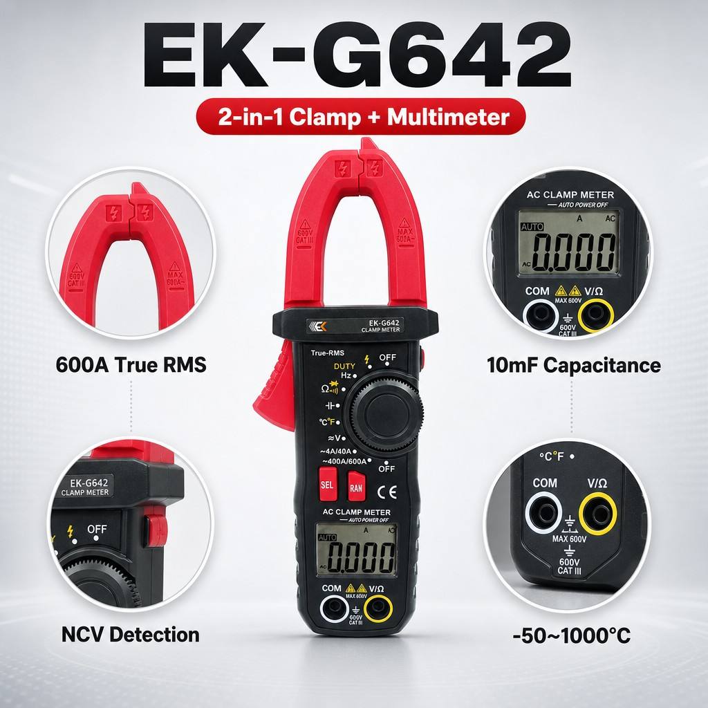
| What are the circuit voltage, load current, resistance, continuity, frequency, or temperature? | Direct electrical measurement or clamp-current measurement | Clamp multimeter | EK-G645 Clamp Multimeter |
| Is AC leakage current present, and how does it behave? | Clamp leakage-current measurement | High-accuracy leakage-current clamp meter | EK-G668A Clamp Leakage Current Meter |
| What is the insulation condition of a cable, motor, generator, transformer, or other high-voltage asset? | Insulation resistance and timed insulation tests | High-voltage insulation resistance tester | EK-C352C High Voltage Insulation Meter |
| What is the resistance of an eligible multi-ground loop without disconnecting the grounding down lead? | Clamp earth-loop resistance measurement | Clamp earth tester | EK-B200X Clamp Earth Tester |
| Which component shows an abnormal surface-temperature pattern under comparable operating conditions? | Infrared thermography | Handheld thermal imager | EK-R384 Handheld Infrared Thermal Imager |
| Are harmonics, voltage swell or sag, interruptions, transients, unbalance, flicker, or inrush current involved? | Multi-channel power-quality measurement and recording | Power quality analyzer | EK-F500 Power Quality Analyzer |
This table is a selection map, not a substitute for the asset manufacturer’s procedure or a site-specific risk assessment. Confirm the required measurement range, circuit category, environmental rating, accessories, and applicable standards before connecting any instrument.
How Should Electrical Testing Be Prepared Safely?
Electrical testing can expose personnel to shock, arc, stored-energy, and equipment hazards. Only qualified persons should perform testing work on electrical circuits or equipment. Where exposed live parts may be encountered, use the safety-related work practices required by the employer, local regulations, and the site’s electrical safety program.
The U.S. Occupational Safety and Health Administration states in OSHA 1910.333 that live parts to which an employee may be exposed should be de-energized before work unless de-energizing creates additional hazards or is infeasible under the stated conditions. It also requires a qualified person to use test equipment to verify the de-energized condition before equipment is treated as de-energized.
OSHA 1910.334 requires test instruments, leads, probes, cables, and connectors to be visually inspected for defects before use and requires them to be rated for the circuits and environment to which they will be connected.
Pre-test checklist
- Define whether the measurement requires an energized or de-energized system.
- Identify normal, backup, backfeed, induced, and stored-energy sources.
- Apply the approved lockout/tagout and verification procedure when required.
- Inspect the instrument, leads, probes, clamp jaw, connectors, insulation, and accessories.
- Confirm the measurement category, voltage/current limit, signal type, and environmental suitability.
- Use the required PPE, barriers, insulated tools, body position, and approach boundaries.
- Stop if the circuit identity, energy state, system documentation, or safe access is uncertain.
How Do You Measure Voltage, Current, Continuity, and Resistance?
General-purpose electrical measurements are often the first diagnostic layer. They establish whether the expected supply exists, how much current the load draws, whether a conductor path is continuous, and whether a component’s resistance is plausible.
Voltage measurement
- Confirm AC or DC mode and select the appropriate range.
- Check that the meter, probes, and leads are rated for the circuit.
- Use the required tester-verification sequence for absence-of-voltage work.
- Measure all specified phase-to-phase, phase-to-neutral, or phase-to-ground points rather than generalizing from one reading.
- Record the connection points and the system’s operating state.
Clamp-current measurement
- Select AC or DC current as required.
- Clamp around one conductor unless the approved method specifically requires another arrangement.
- Close the jaw completely and center the conductor where practical.
- Record load state and compare phases only under comparable conditions.
The EK-G645 combines a clamp meter and multimeter. Its official page lists AC/DC current up to 1200 A, AC/DC voltage ranges up to 1000 V, True RMS AC conversion, resistance, continuity, capacitance, frequency, temperature, diode, NCV, data hold, and surge-signal measurement. Use only functions and ranges appropriate to the application and follow the product instructions.
Continuity and resistance measurement
Continuity and resistance tests are generally performed on a de-energized circuit after absence of voltage has been verified. Isolate parallel paths or connected electronics when required by the equipment procedure. A continuity tone confirms a conductive path; it does not prove that the path has acceptable resistance under operating load.
How Do You Measure Leakage Current?
Leakage-current testing helps investigate current flowing outside the intended load path. The conductor arrangement is essential: clamping one conductor measures its current, while an approved residual-current method may enclose the relevant live conductors so their normal load currents cancel and the remaining value represents imbalance.
The EK-G668A High Accuracy Clamp Leakage Current Meter official page lists AC leakage-current, earth-leakage-current, current, harmonic, True RMS, filter, maximum/minimum/average, distortion-rate, data-hold, and Bluetooth functions. For model EK-G668A, the comparison table lists an AC range from 0.00 mA to 2000 A with 0.01 mA resolution and an 80 mm × 80 mm clamp size.
A leakage-current reading does not identify the root cause by itself. Confirm the conductor arrangement, operating state, filters or drives in the circuit, bonding configuration, and manufacturer limits before deciding whether a value is abnormal.
How Do You Perform Insulation Resistance Testing?
Insulation resistance testing applies a controlled DC test voltage and measures resistance through the insulation system. It is commonly used for cables, motors, generators, transformers, switches, and other assets after they have been isolated according to the relevant procedure.
Recommended insulation-test workflow
- Identify the asset and approved test voltage.
- De-energize, isolate, lock out, and verify absence of voltage.
- Disconnect or protect sensitive electronics, surge devices, and other components as specified by the manufacturer.
- Account for stored energy and capacitance.
- Connect the tester using the approved lead arrangement.
- Run the required spot, timed, PI, DAR, step-voltage, ramp, or discharge test.
- Allow or perform the specified discharge before touching the circuit.
- Record test voltage, duration, resistance, temperature, humidity, asset ID, and connection points.
- Compare with manufacturer criteria and normalized historical results.
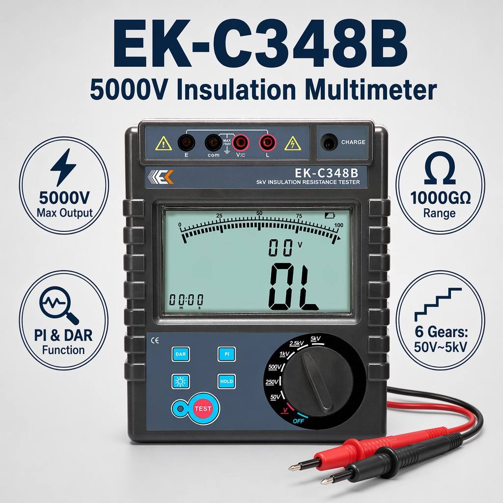
The EK-C352C High Voltage Insulation Meter official page lists rated output-voltage gears of 50 V, 250 V, 500 V, 1 kV, 2.5 kV, 5 kV, 10 kV, and 15 kV, with a listed insulation-resistance range of 0.005 MΩ to 30 TΩ. It lists IR, PI, DAR, STEP, RAMP, DD, AC/DC voltage, and capacitance functions.
The page also lists automatic discharge after testing, a rule that prohibits testing when monitored terminal voltage exceeds 36 V, storage for 1,000 timestamped records, and isolated USB and Bluetooth communications. These functions can support a structured insulation-record workflow; they do not determine the acceptance limit for a specific asset.
Do not compare insulation readings taken at different temperatures, humidity levels, test voltages, or durations without accounting for those differences. Trend analysis is useful only when the test conditions and normalization method are documented.
How Do You Measure Ground or Earth Resistance?
Grounding tests use different methods for different system configurations. A clamp earth tester does not replace every fall-of-potential, selective, or soil-resistivity method. Clamp testing requires an eligible closed grounding loop with parallel return paths; an isolated single electrode may require another method.
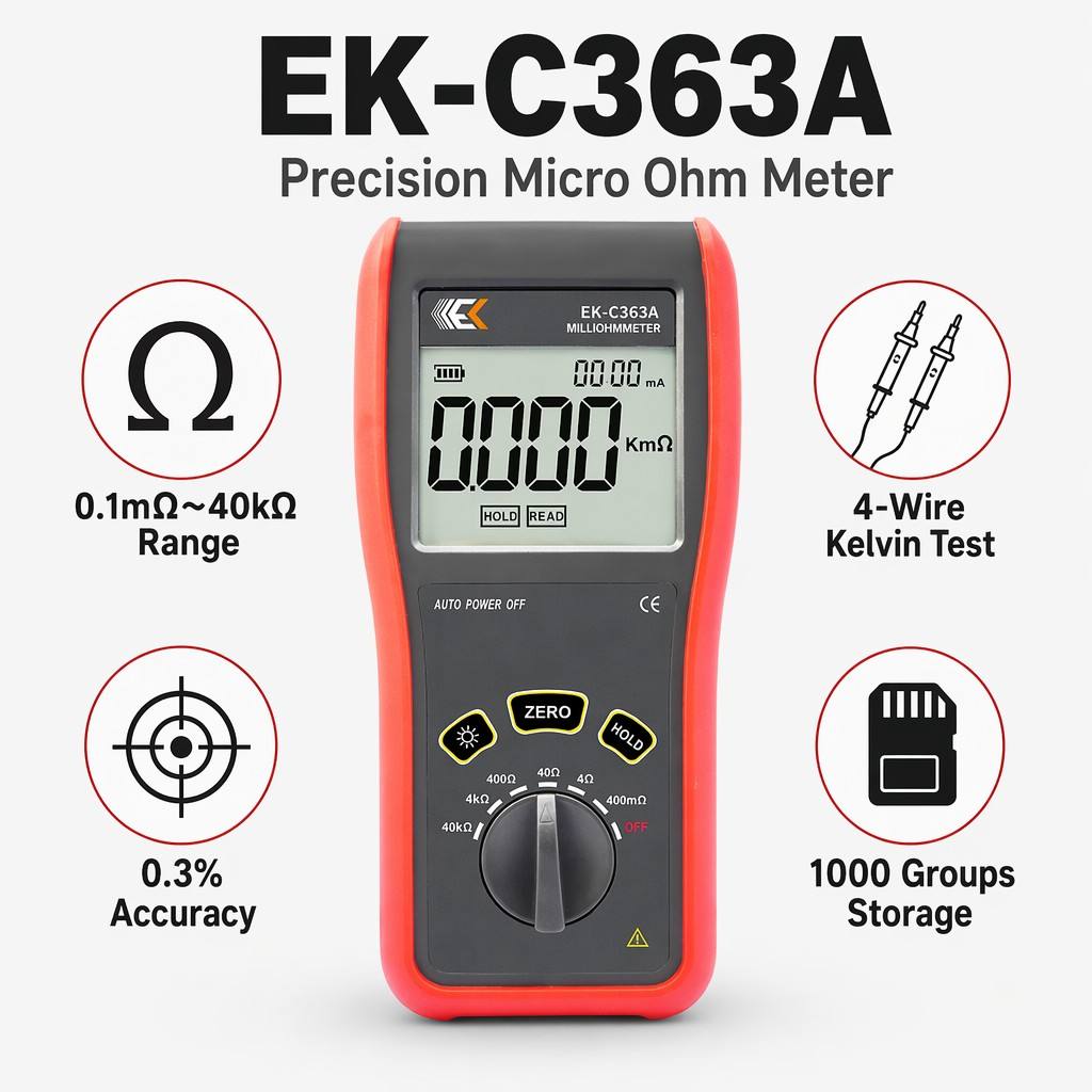
The EK-B200X Clamp Earth Tester is specified for earth-resistance and loop-resistance measurement. Its official page lists a 0.010 Ω to 500 Ω resistance range, 99-group data storage, audible/visual alarm, and a 1 Ω to 199 Ω configurable alarm threshold. The product page states that, for a loop earth system, measurement can be performed without disconnecting the grounding down lead or adding an auxiliary electrode.
Before using a clamp method, confirm that the grounding topology provides a valid loop and that the site procedure allows the measurement. Interpret the result against the design, applicable code, engineering study, and approved acceptance criteria.
How Does Thermal Imaging Support Electrical Inspection?
Thermal imaging is a non-contact method for comparing surface-temperature patterns. It can help prioritize follow-up on connections, breakers, conductors, motors, bearings, and other components, especially when comparable components are operating under similar load.
The EK-R384 Handheld Infrared Thermal Imager official page lists a 384 × 288 infrared detector, temperature ranges of -20°C to 120°C and 120°C to 550°C, adjustable emissivity from 0.01 to 1.00, hot/cold-spot tracking, manual focus, infrared/visible/mix/picture-in-picture display modes, and 16 GB internal storage.
Thermal-inspection context to record
- Asset and component location
- Electrical load and operating state
- Comparable component or phase
- Surface material and emissivity setting
- Reflections, airflow, distance, focus, and viewing angle
- Visible-light reference image where useful
A hot spot indicates a temperature difference, not a confirmed failure mechanism. Follow it with the appropriate electrical, mechanical, connection, or load investigation.
When Is a Power Quality Analyzer Required?
A clamp meter can show an instantaneous voltage or current value, but intermittent disturbances and waveform problems require recording and event analysis. Use a power quality analyzer when the question involves harmonics, voltage sag or swell, interruptions, transients, unbalance, flicker, power factor, energy, or startup current.
The EK-F500 Power Quality Analyzer official page lists four voltage and four current channels, True RMS measurements, phase diagrams, harmonics through the 50th order, total harmonic distortion, power and energy parameters, flicker, three-phase unbalance, transient capture, startup-current monitoring, trend recording, and USB communication.
Measurement setup matters. Record network type, wiring configuration, clamp direction, current-sensor model and ratio, voltage connections, recording interval, trigger thresholds, and monitoring duration. A power-quality report should connect each recorded event to a time, operating condition, and engineering question.
How Should Electrical Test Results Be Recorded?
A useful record allows another qualified person to understand what was tested and reproduce the method. Record at least:
- Asset name, ID, location, and circuit
- Date, time, technician, and work order
- Instrument model, serial number, accessories, and calibration status where required
- Test method, range, function, connection points, and settings
- System state, load, battery state, or operating mode
- Temperature, humidity, and other relevant environmental conditions
- Measured values and units
- Approved acceptance criterion or baseline source
- Photos, thermal images, waveforms, trends, or screenshots
- Observed defects, interpretation, action owner, and retest date
Separate the measured fact from the interpretation. For example, “Phase B measured 18% higher current than Phase A under the recorded operating condition” is a measured comparison. “The motor winding has failed” is a diagnosis that requires additional evidence.
What Common Electrical Testing Mistakes Should Be Avoided?
- Testing without a defined decision or acceptance criterion
- Using an instrument that is not rated for the circuit or environment
- Skipping visual inspection of the meter, leads, probes, connectors, or clamp jaw
- Treating a circuit as de-energized without performing the approved verification
- Using continuity or resistance mode on an energized circuit
- Applying insulation test voltage to connected electronics without confirming suitability
- Using a clamp earth method where no valid loop exists
- Comparing thermal images taken at different loads without noting the difference
- Changing power-quality wiring or clamp direction without documenting the setup
- Diagnosing a root cause from one abnormal reading
- Recording values without units, test points, conditions, or instrument settings
- Failing to assign and verify corrective action
Frequently Asked Questions
What is the first step in electrical testing?
Define the decision the test must support. Identify the asset, expected condition, required measurement, safety state, acceptance criterion, and follow-up action before selecting an instrument.
Can one electrical tester handle every maintenance task?
No. A clamp multimeter, leakage-current meter, insulation tester, earth tester, thermal imager, and power quality analyzer answer different questions. Select the test method first, then choose a suitable instrument.
What is the difference between continuity and insulation resistance?
Continuity verifies that a conductive path exists, usually with low resistance. Insulation resistance evaluates resistance through an insulating system using a specified DC test voltage. The procedures, instruments, safety controls, and acceptance criteria are different.
Can a thermal imager replace electrical measurements?
No. Thermal imaging identifies surface-temperature patterns and supports prioritization. Electrical measurements, inspection, load data, and component-specific checks are needed to investigate the cause of an abnormal pattern.
When should a power quality analyzer be used instead of a clamp meter?
Use a power quality analyzer when the problem involves waveform shape, harmonics, transient events, voltage sag or swell, interruptions, unbalance, flicker, inrush, or long-term trends. A clamp meter is better suited to direct spot measurements within its listed functions.
Why are test conditions important for trend analysis?
Load, temperature, humidity, test voltage, duration, connection point, sensor type, and instrument settings can change the result. Trends are meaningful only when those conditions are recorded and comparisons are made on a valid basis.
How can electrical testing content be made easier to audit and cite?
Use clear definitions, question-based headings, reproducible procedures, measurement units, model-specific specifications, linked primary sources, visible revision dates, and explicit separation between measured facts and engineering interpretation.
Conclusion
Effective electrical testing combines safety control, method selection, instrument suitability, consistent measurement, and traceable documentation. Start with the engineering question, choose the correct test category, record the conditions, and compare results with an approved criterion or a valid baseline.
EK Instruments provides dedicated tools across several parts of this workflow, including clamp measurement, leakage-current testing, insulation resistance, earth-loop resistance, thermal imaging, and power quality analysis. The product links in this guide lead to the official specifications so readers can confirm whether a model matches their circuit, asset, and procedure.
Sources and Technical References
- OSHA 1910.333 — Selection and use of work practices
- OSHA 1910.334 — Use of equipment
- EK-G645 Clamp Multimeter — official product specifications
- EK-G668A Clamp Leakage Current Meter — official product specifications
- EK-C352C High Voltage Insulation Meter — official product specifications
- EK-B200X Clamp Earth Tester — official product specifications
- EK-R384 Handheld Infrared Thermal Imager — official product specifications
- EK-F500 Power Quality Analyzer — official product specifications