Recursos
How to Measure Ground Loop Resistance Without Disconnecting the Grounding Conductor
2026年08月07日
A field guide to clamp-on ground resistance testing for multi-grounded systems. It explains the closed-loop requirement, compares the method with fall-of-potential testing, provides a repeatable seven-step workflow, and uses the EK-B200X as a product-selection example.
Direct answer: A clamp-on ground resistance tester measures the resistance of a complete grounding loop without disconnecting the grounding conductor or installing auxiliary test stakes. It is fast and practical for multi-grounded systems, but it requires a closed return path. It is not the correct method for an isolated single ground electrode.
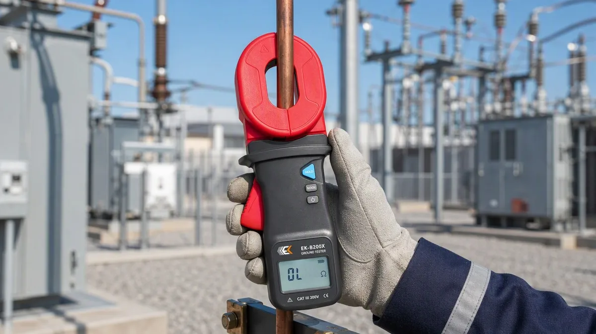
Grounding systems can deteriorate because of corrosion, loose connections, soil changes, mechanical damage, or modifications elsewhere in the network. The difficulty is that a conventional test may require the grounding conductor to be disconnected or auxiliary stakes to be placed in the soil—steps that may be impractical during routine maintenance.
Clamp-on ground resistance testing provides another option. When the grounding arrangement forms a valid closed loop, a technician can clamp around the grounding conductor, obtain a loop-resistance reading, and continue the inspection without opening the grounding connection.
The convenience is real, but so is the limitation: the instrument measures the complete loop seen through the clamp, not automatically the isolated resistance of one electrode. A useful result therefore depends on understanding the grounding topology before interpreting the number.
This guide explains what the method measures, when it is valid, how it differs from fall-of-potential testing, and how the EK-B200X clamp earth tester can be evaluated for field maintenance work.
What Does a Clamp-On Ground Resistance Tester Actually Measure?
Definition: Clamp-on ground resistance testing induces a test signal into a closed grounding loop and measures the resulting response to calculate loop resistance. The measured path includes the electrode or branch under test, the soil, other parallel grounding paths, and the bonding conductors that complete the return circuit.
A clamp earth tester typically contains both a signal-generating function and a measuring function within the jaw assembly. Once the jaw is fully closed around the grounding conductor, the instrument applies a known test signal to the loop, senses the resulting current, and calculates resistance using the relationship between voltage and current.
A simplified current path is:
Grounding conductor under test → connected electrode → soil → other bonded electrodes → grounding network → return to the test point
That path explains why the method is often called stakeless ground resistance testing or ground loop resistance measurement. No temporary reference stakes are needed, but the existing grounding system must provide the return path.
It also explains an important interpretation rule. If one electrode has resistance Rx and the rest of the grounding network forms an equivalent return resistance Rp, the clamp sees the loop approximately as:
Rloop = Rx + Rp
In a system with many effective parallel electrodes, Rp may be relatively small, so the reading can be useful for identifying a deteriorated branch and tracking changes over time. However, it should not be described as an isolated-electrode value unless the network and method justify that interpretation.
When Is the Clamp-On Method Appropriate?
Short answer: Use clamp-on testing when the grounding system has multiple bonded paths that create a closed loop, and when the maintenance objective is to check loop condition without disconnecting the conductor. Use another method when the electrode is isolated or when the required result is the independent resistance of a new electrode.
| Site condition | Suitable for clamp-on testing? | Why |
|---|---|---|
| Multiple electrodes are bonded in parallel | Yes | The network can provide a test-current return path |
| The grounding conductor should remain connected during routine inspection | Often yes | The clamp can measure without opening the grounding connection |
| Auxiliary stakes cannot be installed because of paving, traffic, or restricted access | Often yes | The stakeless method does not require temporary probes |
| A single isolated ground rod has no parallel return path | No | The test circuit is open, so the method cannot produce a valid loop measurement |
| A new electrode requires an independent commissioning measurement | Usually not by clamp alone | The test objective may require fall-of-potential or another approved method |
| The grounding topology is unknown | Not yet | Confirm the current path before trusting or interpreting the reading |
Typical candidates include multi-grounded building systems, interconnected lightning-protection networks, telecommunications sites, utility structures, street-lighting networks, and industrial grounding grids. These are potential applications, not automatic approvals: the technician must first confirm that the actual installation provides a valid closed loop.
A fast pre-test decision check
Before placing the clamp, answer three questions:
- Is there more than one effective path to earth?
- Are those paths bonded so the test signal can return to the clamp?
- Does the inspection require a loop check, or an isolated-electrode measurement?
If the answer to either of the first two questions is no, or if the required result is an isolated-electrode value, select a different test method.
Clamp-On vs. Fall-of-Potential Testing
Neither method is universally “better.” The correct method depends on the grounding structure, available space, test objective, and governing maintenance procedure.
| Decision factor | Clamp-on / stakeless method | Fall-of-potential method |
|---|---|---|
| Auxiliary test stakes | Not required | Required |
| Closed return loop | Required | Does not depend on an existing parallel loop |
| Grounding conductor disconnection | Normally not required for the loop test | May be required to isolate the electrode, depending on the procedure |
| Best fit | Routine checks and trending on multi-grounded systems | Isolated electrodes, commissioning, and independent resistance measurement |
| Field setup | Fast and compact | Requires space, test leads, probe placement, and more setup time |
| Main interpretation risk | Treating loop resistance as an isolated-electrode value | Poor probe placement, overlapping influence areas, or unintended parallel paths |
The Fluke earth-ground testing guide describes the stakeless method as suitable for multiple grounds connected in parallel and explicitly notes that it is not suitable for an isolated ground system. A technical comparison published by EE Power likewise emphasizes that a measurable loop must exist for a clamp-on tester to operate correctly.
For maintenance teams, the practical approach is often complementary:
- Use clamp-on testing for efficient route-based inspections and trend monitoring where the topology is valid.
- Use fall-of-potential or another approved method when an independent electrode value is required, the system is isolated, or the clamp result is inconsistent with the asset history.
How to Measure Ground Loop Resistance Step by Step
The following workflow is a general field framework. It does not replace the instrument manual, applicable standards, site safety rules, or a task-specific risk assessment.
1. Confirm the grounding topology
Review the drawing or trace the conductors to verify that the electrode under test is connected to other effective grounding paths. Do not assume that a visible bond automatically creates a valid return loop.
If the site has only one isolated electrode, stop and select an appropriate stake-based or approved alternative method.
2. Define the purpose and acceptance criteria
Decide whether the task is a routine loop check, a comparison between branches, an investigation of a suspected fault, or an independent acceptance test. The purpose determines whether the clamp-on method can answer the question.
Do not apply one universal “acceptable ohm value” to every site. The limit should come from the system design, equipment manufacturer, governing standard, local code, or the organization’s approved maintenance procedure.
3. Review safety requirements and instrument ratings
Inspect the test location for exposed conductors, induced voltage, damaged insulation, wet surfaces, traffic, and other hazards. Follow the site’s isolation and personal-protective-equipment requirements.
Before using any tester near an energized installation, verify the instrument’s documented electrical ratings and the approved procedure. The public EK-B200X product sheet identifies double insulation but does not list a CAT rating or detailed live-system procedure; obtain and follow the full operating documentation for the intended application.
4. Inspect the tester and jaw surfaces
Check the housing, display, battery condition, and jaw mechanism. The mating surfaces must be clean and able to close completely. Dirt, corrosion, damage, or a visible gap can affect the magnetic circuit and lead to unstable or misleading results.
The EK-B200X package includes a standard calibration loop. Use that accessory only according to the operating instructions as a pre-use check; it does not replace scheduled calibration or the organization’s metrology requirements.
5. Select a representative test point
Clamp around one grounding conductor or one intended branch at a point that represents the asset being evaluated. Avoid surrounding multiple conductors unless the approved method specifically requires it, because opposing current paths or unintended parallel paths can change the result.
Confirm that the conductor fits within the jaw and that the clamp can close without force or misalignment.
6. Close the jaw completely and take the reading
Close the jaw fully, keep the instrument stable, and allow the display to settle. Repeat the measurement at the same point to check consistency. If the reading fluctuates significantly, inspect the jaw, test position, nearby current paths, and grounding topology before recording a result.
7. Compare, document, and trend
A single number has limited diagnostic value without context. Record:
- Asset ID and test-point location
- Date and time
- Grounding topology or branch description
- Weather and relevant environmental conditions
- Instrument model and serial number
- Calibration or pre-use check reference
- Repeated readings
- Acceptance criterion and its source
- Pass, investigate, or retest decision
Trend data from the same point under comparable conditions. A meaningful increase from the established baseline can justify inspection even when the reading remains below a general project limit.
Using the EK-B200X as a Field Example
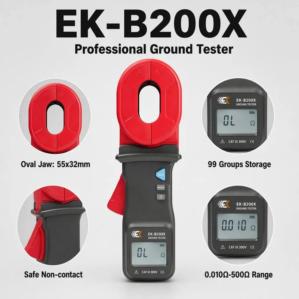
The EK-B200X is designed for earth-resistance and loop-resistance measurement in systems where the clamp-on method is valid. Its published specifications include:
| Published specification | EK-B200X value | Field-selection relevance |
|---|---|---|
| Resistance range | 0.010 Ω to 500 Ω | Covers low-resistance loops and higher-resistance conditions within the published range |
| Minimum resolution | 0.001 Ω from 0.010 Ω to 0.099 Ω | Provides fine display increments in the lowest published range |
| Single measurement time | 0.5 s | Supports route-based field checks |
| Data storage | 99 groups | Allows multiple readings to be retained during an inspection route |
| Alarm threshold setting | 1 Ω to 199 Ω | Supports rapid screening against a user-defined project threshold |
| Jaw dimensions | 55 × 32 mm | Helps buyers evaluate the physical jaw geometry |
| Maximum jaw opening | 32 mm | The target conductor must fit while allowing the jaw to close fully |
| Power supply | Four LR6 1.5 V alkaline batteries | Uses commonly available field-replaceable batteries |
| Included accessories | Standard calibration loop, case, four LR6 batteries | Supports transport and the documented pre-use workflow |
Full accuracy varies by resistance range. Buyers should review the EK-B200X datasheet, rather than selecting a tester from maximum range alone.
Three specifications deserve particular attention during selection:
Jaw opening
The 32 mm maximum opening is a physical fit limit, not a statement that every 32 mm conductor shape will be equally easy to clamp. Check the actual round conductor, grounding strip, joint, and working clearance at the intended test point.
Low-range performance
A broad maximum range does not describe performance across the entire scale. Compare resolution and accuracy in the resistance range that matters for the site. The EK-B200X publishes separate accuracy bands from 0.010 Ω through 500 Ω.
Storage and alarm functions
The 99-group storage and adjustable alarm threshold can speed up repeated inspections. The alarm is a screening tool: its threshold should be set from an approved project criterion, not from an assumed universal value.
What Causes Unreliable or Misleading Clamp-On Readings?
1. No closed return path
This is the most fundamental failure condition. An isolated electrode does not provide the loop needed by a stakeless tester.
2. The jaw is not fully closed
Contamination, damage, or poor positioning can leave a gap in the magnetic path. Clean and inspect the jaw surfaces, then repeat the test.
3. Multiple conductors are inside the jaw
Clamping around more than the intended branch may combine or cancel current paths. The result may no longer represent the branch the technician intended to inspect.
4. The loop is mistaken for one electrode
The reading includes the return network. Record it as loop resistance unless the test design supports a more specific interpretation.
5. The system changed since the previous test
New bonds, removed conductors, temporary connections, or equipment modifications can change the parallel return resistance even when the electrode itself has not deteriorated.
6. Environmental conditions are ignored
Soil moisture, temperature, and seasonal conditions can affect grounding performance. Compare readings under similar conditions or document the differences.
7. One reading is treated as a final verdict
Repeat the measurement and compare it with historical results, adjacent branches, and the approved acceptance criterion. Investigate unexpected values rather than forcing them into a pass/fail assumption.
Where Can Clamp-On Ground Testing Add Value?
Telecommunications and communication sites
Multiple bonded grounding paths may exist across towers, equipment shelters, and service infrastructure. Clamp-on testing can support route-based maintenance if the closed loop is confirmed.
Lightning-protection networks
A building may have several bonded down conductors and electrodes. The clamp-on method can help compare branches without opening the protection network, but the complete system arrangement must be understood before interpreting the result.
Industrial plants and distribution systems
Production sites often prioritize continuity and fast maintenance access. A clamp earth tester can support periodic checks of valid multi-grounded loops where stake placement or disconnection is impractical.
Utility, rail, and transportation assets
Distributed assets can involve repeated inspection points and limited access. Fast measurement and onboard storage may improve field efficiency, provided each location meets the method’s loop requirement and the organization’s approved procedure.
These examples describe possible use cases, not a claim of suitability for every installation. Review the actual conductor size, grounding topology, electrical environment, required safety rating, and governing procedure before selecting the instrument.
How Should You Choose a Clamp Earth Tester?
Use a selection checklist that connects the instrument to the job:
- Measurement objective: loop maintenance check or independent electrode test?
- Grounding topology: is there a verified closed return path?
- Expected resistance range: what range matters, and what accuracy applies there?
- Conductor fit: will the jaw open, surround the conductor, and close completely?
- Field workflow: are storage, hold, alarm, and measurement speed useful for the inspection route?
- Safety documentation: are the electrical ratings and operating limits appropriate for the site?
- Metrology: what calibration documentation and verification process does the organization require?
- Support: can the manufacturer review the application, conductor size, and grounding diagram before purchase?
For product dimensions, published accuracy bands, and included accessories, see the EK-B200X product specifications. You can also browse EK Instruments’ electrical test-instrument range or review the company’s R&D and manufacturing background.
Frequently Asked Questions
Can a clamp ground tester measure a single isolated ground rod?
No. A clamp-on or stakeless tester requires a closed return path. If the rod is truly isolated and has no effective parallel grounding path, use fall-of-potential or another method approved for the required measurement.
Does clamp-on ground testing require auxiliary stakes?
No. The method uses the existing grounding network as the test-current path, so temporary auxiliary stakes are not required. That convenience applies only when the network forms a valid closed loop.
Do I need to disconnect the grounding conductor?
Normally not for a valid clamp-on loop test. Avoiding disconnection is one of the method’s main field advantages. Always follow the instrument instructions and the site’s approved procedure.
What is the difference between ground resistance and ground loop resistance?
Ground resistance may refer to the resistance of an electrode or grounding system to earth. Ground loop resistance is the resistance of the complete path measured through the clamp, including the target branch and the parallel return network. The terms should not be treated as automatically interchangeable.
Why can readings change at different points on the same grounding system?
Different clamp positions can include different conductors, bonds, electrodes, and parallel return paths. Local connection condition and environmental factors can also change the measured loop. Record the exact test point so future readings are comparable.
How often should grounding resistance be tested?
Use the interval defined by the applicable standard, asset criticality, site conditions, manufacturer requirements, and the organization’s maintenance program. Harsh environments or rapidly changing trends may justify more frequent inspection.
What conductor size can the EK-B200X clamp around?
The published maximum jaw opening is 32 mm, and the stated jaw dimensions are 55 × 32 mm. Confirm the actual conductor or grounding strip shape and the available working clearance; the jaw must surround the intended conductor and close completely.
Turn the Measurement into a Reliable Maintenance Decision
Clamp-on testing is valuable because it can reduce setup time and keep a valid grounding connection intact during routine checks. Its speed does not remove the need for engineering judgment. The technician must verify the loop, select a representative test point, understand what the reading includes, and compare the result with an approved criterion and historical data.
For a possible EK-B200X application:
- Review the full product page.
- Download the EK-B200X datasheet.
- Confirm that the target conductor fits the 32 mm jaw opening.
- Send EK Instruments your grounding diagram, conductor dimensions, application, and required quantity for technical selection support.
Technical and commercial contact: Jemma@ek-instruments.com